

I have watched a lot of shell and tube exchangers get pulled apart for cleaning, and the difference between a bundle that lasts fifteen years and one that fails in five is almost never the shell. It is the bundle. Tube diameter, wall thickness, pitch, material, and the way the bundle is supported inside the shell decide how the unit performs, how often it fouls, and how easy it is to maintain. So instead of another overview, let me put down what actually decides the outcome.
A shell and tube exchanger has one fluid inside the tubes and the other flowing across them inside the shell. The bundle is the surface area where the heat transfer happens. Everything else, the shell, the heads, the nozzles, exists to bring the two fluids to that surface.
That means the bundle is not a passive part. It sets the heat transfer coefficient on both sides, it sets the pressure drop on both sides, and it sets the mechanical behavior of the whole unit under thermal cycling. Get the bundle right and the exchanger works. Get it wrong and no amount of shell-side tinkering will fix it.
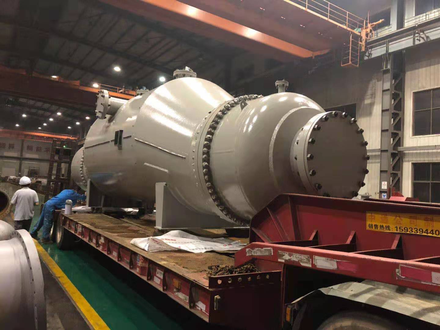
The Decisions That Actually Matter
Most people start by comparing materials. That matters, but it is not the first decision. The first decisions are geometric.
Tube diameter. Smaller tubes give more surface area per unit volume, which means a more compact bundle. They also raise the pressure drop and make mechanical cleaning harder. Larger tubes are easier to clean and cheaper to fabricate, but they need a bigger shell for the same duty. The choice is a trade-off between footprint, pressure drop, and cleaning access. In dirty service, larger tubes usually win, even if the unit is bigger.
Wall thickness. Thicker walls give more corrosion allowance and more mechanical strength, but they add thermal resistance and cost. The thickness has to be chosen against the corrosion rate, the design pressure, and the expected service life. If the corrosion allowance is guessed, the tubes will either fail early or the unit will be unnecessarily expensive.
Tube pitch and layout. Triangular pitch packs more tubes into the same shell, which gives more surface area and more turbulence on the shell side. Square pitch gives a straight lane for mechanical cleaning and tends to foul less in some services. Rotated square pitch is a middle ground. The choice depends on whether the limiting factor is thermal performance or cleaning access.
Tube material. Carbon steel, stainless, duplex, titanium, and high alloys all behave differently. The material has to be compatible with both fluids, and it has to survive the operating temperature. Chlorides are the usual failure mode for stainless, and they often come from the cooling water rather than the process fluid. If chlorides are present on either side, the material selection changes.
Bundle support and baffle design. Baffles set the shell-side flow path. They determine the crossflow velocity, the pressure drop, and whether the bundle vibrates. Poor baffle design causes vibration, tube wear at the baffle edges, and premature failure. This is one of the most common causes of tube failure I have seen, and it is decided at the design stage.
What Actually Determines Whether the Bundle Lasts
The datasheet will give you the tube count and the material. It will not tell you the things that decide whether the bundle survives.
Vibration analysis.
Flow-induced vibration is the leading cause of tube failure in shell and tube exchangers. It happens at the baffle edges, at the inlet nozzle, and in the U-bend. If the bundle was not analyzed for vibration, it may fail even if every other parameter is correct.
Fouling behavior.
The tube surface, the pitch, and the velocity determine how fast the bundle fouls. A bundle that runs at low shell-side velocity will foul faster than one that runs at higher velocity. In dirty service, the cleaning method and access matter as much as the thermal design.
Corrosion and erosion.
Tube inlets are vulnerable to erosion from high-velocity flow, especially if the fluid carries solids. Tube walls are vulnerable to corrosion from the shell-side fluid or from the cooling water. Both have to be assessed against the actual fluids, not a general compatibility chart.
Thermal cycling.
Every startup and shutdown puts the bundle through a thermal cycle. The tubes expand and contract, the tubesheet follows, and the bundle support has to allow that movement without wearing the tubes. In cyclic service, the bundle support detail is critical.
Installation and Operation
Most bundle problems I have seen were installation or operation problems, not design problems.
The bundle has to slide into the shell without damage to the tubes or the baffles. The tubesheet has to be aligned and the gaskets have to be seated correctly. The piping has to be aligned so it does not load the nozzles. On U-tube bundles, the U-bend area deserves extra attention because it is the hardest area to inspect and clean.
Once in service, the routine matters more than the hardware. Monitor pressure drop and temperature approach. A rising pressure drop is usually the first sign of fouling on the shell side. A drifting temperature approach means the bundle is losing performance. Clean on a defined interval based on actual operating data, not on a generic schedule. Inspect tubes for vibration wear, erosion, and corrosion on a regular basis, especially at the baffle edges and the inlet ends.