

Segmental baffles have been the default in shell and tube heat exchangers for decades, but they carry known costs: shell-side flow is forced across the bundle in a zigzag path, which produces high pressure drop, creates dead zones behind each baffle, and promotes fouling in those zones. The helical baffle is an alternative that changes the shell-side flow path itself rather than adjusting the conventional one. This article explains how the design works, what it changes in practice, and where it is and is not the right choice.
How the Helical Baffle Changes Shell-Side Flow
In a conventional exchanger, segmental baffles are perpendicular plates with cutouts that force fluid to cross the bundle repeatedly. Each pass through the bundle produces turbulence and heat transfer, but also pressure loss, and the region behind each baffle is a low-velocity zone where deposits collect.
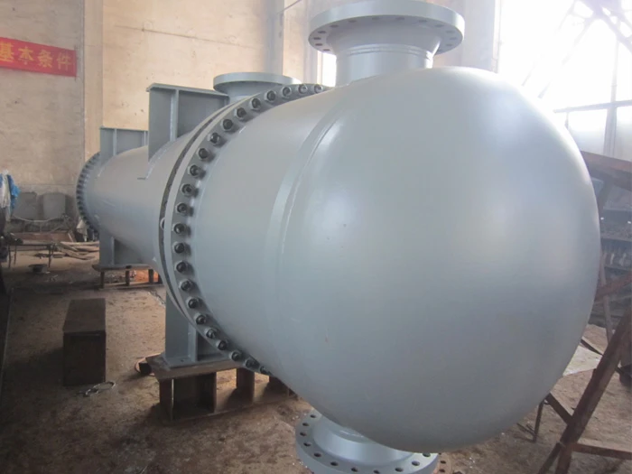
A helical baffle is a set of inclined plates arranged so that the shell-side fluid follows a spiral path around the bundle. The flow is still directed across the tubes, but continuously and at an angle, rather than in discrete cross-flow passes. This changes three things at once: the pressure drop per unit of heat transfer, the distribution of shell-side velocity, and the location of low-velocity regions.
What Changes in Practice
- Pressure drop versus heat transfer. The spiral path reduces the number of sharp flow reversals the shell-side fluid undergoes. In many services this lowers shell-side pressure drop for a given heat transfer duty, which reduces pump or compressor power. The size of the reduction depends on baffle helix angle, baffle pitch, and the flow rate relative to design, so it should be evaluated for the specific duty rather than assumed.
- Fouling behavior. Segmental baffles create recirculation zones behind each plate where particulate matter settles. The helical arrangement avoids those discrete dead zones, which can extend the interval between cleanings in services with particulate or precipitating foulants. It does not eliminate fouling, and services with strong chemical or biological fouling still require scheduled cleaning.
- Shell-side velocity distribution. A continuous spiral path produces more uniform shell-side velocity than the pass-by-pass pattern of segmental baffles. More uniform velocity means fewer low-velocity regions that contribute little to heat transfer while still occupying bundle volume.
- Footprint. Where the pressure drop limit rather than the heat transfer area sets the exchanger size, a lower pressure drop per unit area can allow a smaller shell for the same duty. Whether this is realized depends on the relative importance of pressure drop and area in the specific design.
Where the Design Fits
Helical baffles are most useful where shell-side pressure drop is a binding constraint, where fouling in low-velocity zones is a known problem, or where both apply. Chemical processing, refining, power generation, and HVAC systems all contain such services.
The design is less clearly advantageous where shell-side pressure drop is not limiting, where the fluid is clean and fouling is not a concern, or where the duty is small enough that the added design effort is not justified. It is also not a substitute for correct material selection in corrosive service.
Design and Operating Considerations
Lorem ipsum dolor sit, amet consectetur adipisicing elit.
Helix angle and baffle pitch. These two parameters set the balance between heat transfer and pressure drop. Smaller helix angles increase cross-flow velocity and heat transfer but raise pressure drop. The optimum depends on the fluid properties, flow rate, and the relative cost of area versus pumping power, and should be determined by calculation for the specific duty.
Tube layout and support. The baffle plates also support the tubes. Confirm that support spacing is adequate to prevent flow-induced vibration at the design shell-side velocity, since a continuous spiral path can produce different vibration excitation than segmental cross-flow.
Materials. Baffle and tube materials must be selected against the actual fluid chemistry. Reduced fouling does not compensate for inadequate corrosion resistance.
Instrumentation. Monitor shell-side pressure drop and terminal temperature difference over time. A rising pressure drop or falling temperature difference at constant flow indicates fouling and should trigger inspection rather than continued operation at degraded duty.

Limitations
The helical baffle is a flow-path change, not a universal improvement. Its benefits depend on the duty: the pressure drop advantage is largest where the conventional design is pressure-drop limited, and the fouling advantage is largest where low-velocity zones are the dominant fouling mechanism. In clean service with generous pressure drop allowance, the performance difference may not justify the design and fabrication cost. Claims of reduced energy use should be checked against calculated pump or compressor power for the actual flow and head, not accepted as a general property of the design.
Conclusion
Helical baffles change the shell-side flow path from discrete cross-flow passes to a continuous spiral. The practical effects are lower pressure drop per unit of heat transfer, more uniform shell-side velocity, and fewer low-velocity zones where fouling collects. These effects are real but duty-dependent: they are largest where pressure drop is limiting or where dead-zone fouling dominates. Specifying helix angle and pitch by calculation for the actual fluid and flow rate, confirming tube support against vibration, and monitoring pressure drop and temperature difference in service are what convert the design's potential into measured performance and energy savings.